Electrical circuits become comprehensible once we get a good mental picture of what is happening inside them. Here the analogy between an electrical system and a system to deliver water becomes useful.
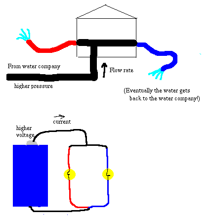
In the preceding sections, we put various devices in series. This means that all the current that goes through one device goes through the other; the current in each device is the same. However, some of the devices are able to operate with a small current through them, while others need a large current -- they are respectively high resistance and low resistance devices, assuming the current is proportional to the applied voltage. When these are put in series with each other, only the low-current device operates, while the high-current device does nothing. We can compare this to a thick hose with a spray nozzle on the end: the water is moving very rapidly through the tiny hole in the spray nozzle, but only very slowly in the hose (for in fact the flow rate is decreased by the resistance the nozzle causes).

In many of the circuits in this section we put devices in parallel. Now each device sees the same applied voltage, and an appropriate current flows through each device. This is like having two hoses (one in the front yard, one in the back yard). It doesn't make much difference to one hose if the other is turned on or not. When they are both turned on, there is a larger flow rate from the water company than when there is just one hose -- it's a bit like having a thicker hose. The resistance seems smaller, from the point of the water company, since more water is flowing for the same pressure. Replacing the words "water company" by "battery, "flow rate" by "current," "pressure" by "voltage," and "hose" by "electrical device," and you will have a description of how parallel circuits behave.
Most of the time, we want electrical devices to work
independently of each other, and so we wire them in parallel. We
usually do not put power-consuming devices in series (as you have
seen, the result generally is that one of them doesn't work).
However, a light switch is in series with the light bulb it
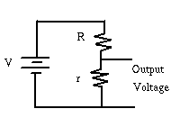
controls. Here is another example of a series circuit:

We are interested in the voltage between the two wires that are
coming out. All the current goes through both resistors: they are
in series. The voltage across each one is proportional to the current through it, and to
its resistance; together they share the voltage of the battery. The share each one gets is
proportional to its resistance. The result is that the output voltage is less than the voltage
of the power source, and varies from being a small fraction to being a big fraction as we
vary the sizes of the two resistors.
This device is called a voltage divider; you didn't know it,
but you have many copies of this device around your house! You have
one in the volume control of your radio, and there probably is one
in the light dimmer; in fact, many of the knobs that you can turn
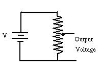
to adjust something work this way. The knob causes a sliding
contact to move along a wire -- a better picture of the device
is

The total resistance R+r isn't changing, and so the output voltage is directly proportional to r.
If we now connect a device to the two output voltage wires, it will run more slowly or be less bright. But now current is flowing through the device, and this is not a simple circuit any more.
Complicated Circuits
The third activity introduced some more complicated circuits. As
an example of how such circuits arise in everyday life, consider
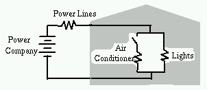
the example shown below:

This represents a house that contains a light bulb and an airconditioner. The house is connected to the power company, which is represented by a battery. The wires connected the house to the power company have a small resistance, but not quite negligible, so this has been indicated in the diagram. The light bulb and the airconditioner are also represented by resistances. Of course the light bulb and the airconditioner are in parallel, so that they can be turned on and off independently. The airconditioner turns itself on and off, depending on the thermostat reading. When it is turned on, it is using a lot of power, so the current to it must be very large: it looks like a small resistance. When the airconditioner is just starting, the current is even bigger, for both mechanical and electrical reasons.
When the airconditioner is off, the light bulb determines the current in the circuit -- it has a higher resistance than the wires to the power company, so that most of the electrical power is delivered to the light bulb. However, it takes some voltage to make this current move through the wires, and so the voltage that the house sees is slightly less than the voltage the power company applies.
When the airconditioner turns on, the power used by the house greatly increases, and so the current passing through the house circuits is larger. All of this current comes down the wires from the power company. To make a larger current move through the resistance of these wires, the voltage difference between power company and house must be larger. This leaves less for the house, and so when the airconditioner starts, the house lights get dimmer (in the fluid flow analogy, this is also why the shower water pressure drops when someone turns on a faucet elsewhere in the house).
You could build your own version of this circuit (replacing all of the resistors by light bulbs), and see for yourself that when you unconnect and reconnect the "airconditioner" the "house lights" get brighter and dimmer, and the "power line" light bulb shows how much current is flowing in each case.
This is the most complicated section of the Virtual Workshop on Electricity and Magnetism. If you would like some more explanation, don't hesitate to email us.
Check the box when you are
done:
Next:Discussion of electrical
circuits