 . When the switch is "up" it connects the wire on the
left to the upper wire on the right, while when it is "down" it
connects to the lower wire. Here is the complete diagram for the
stairway light:
. When the switch is "up" it connects the wire on the
left to the upper wire on the right, while when it is "down" it
connects to the lower wire. Here is the complete diagram for the
stairway light:You have a switch at the bottom of the stairs and a switch at the top of the stairs, and both will turn the stairs light on and off. How does that work?
There are two ingredients to this. First, we need an extra wire
running up the stairs, and second, we need a slightly more
complicated kind of switch, called the "double throw" switch.
Here's a cartoon of this kind of switch:  . When the switch is "up" it connects the wire on the
left to the upper wire on the right, while when it is "down" it
connects to the lower wire. Here is the complete diagram for the
stairway light:


Could you wire three switches so that flipping any one of them would turn a light off and on?
This would allow you to turn the outdoor lights off and on from the
front hall, the kitchen, or the garage.
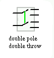
 To do this at all we need a new kind of switch, called the "double-pole
double-throw" switch. It actually is two separate double-throw switches,
with a mechanical connection (represented by the green line) so that you
turn them both "up" or "down" at once.
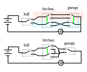
Here are two ways to solve the puzzle:

The first solution is easier to understand. The double-throw switch at left chooses either the circuit in the pink box or the circuit in the blue box. Those circuits are the two we just discussed -- if we choose the pink box, we need both of its switches in the same position to turn on the light; if we choose the blue box, we need the two switches in opposite positions to turn on the light.
The second solution is slightly more elegant, in that it only needs one double-pole, double-throw switch, and only needs two wires running from each switch to the next (whereas the first solution requires four wires running from the kitchen switch to the garage switch). If you wanted something like this at your house, the electrician would most likely solve the problem a third way, by using relays. These are electrically controlled switches (just imagine that you are turning on and off a magnet that flips a switch someplace else). What this would accomplish is that all of the switches and interconnecting wires of the diagrams above get moved close to each other in a relay box (which might be close to the light bulb); the switch in the kitchen would have a single pair of wires running to the relay box, to run the electromagnet that does the actual switch-flipping for you. There would still be, somewhere, an arrangement of switches like the ones shown above.
Why study circuits?
The section on circuits