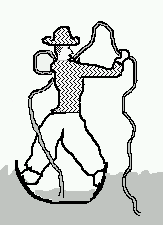
Fluids 1.My friend Bob wants to remove the water from his boat that splashed in when he hooked a fish. He has a hose which he is considering using to siphon the water out. Unfortunately, he doesn't know anything about siphons. Please explain how to get the hose working as a siphon, and discuss the relative merits of using a siphon versus bailing with his hat.
To make a siphon, Bob needs to completely fill the hose with water, which he can do conveniently by lowering it overboard. Then he should stopper one end just long enough to get it linking the water in the boat to the water outside. Water will then start to flow from the higher water level to the lower water level. Most likely this is not what he wants to happen -- he will sink the boat instead of getting the water out!
Note that it is not good enough for the end of the tube to be lower outside the boat. (You could test this with two jugs side by side). The problem is that there is already water where the end of the tube is, and for any to run out, this water has to be pushed away. The only place where there is room for more water is at the surface of the lake, and so this is the level that matters.
However, it is possible that he has a very floaty boat
made of styrofoam or with a large built-in air chamber -- then the
siphon will work for him.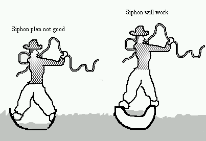
2.Filling a backyard swimming pool is a slow business! My neighbor Margie says you should use the hose nozzle, set to make a stinging jet of water that blasts the paint off the pool, because this will speed the process up. Louise says this won't help at all. Please discuss Margie's idea, and explain who is right.
Margie has confused the speed of the water coming out of the hose for flow rate. Flow rate depends on both the speed and also the cross-sectional area of the stream. The nozzle decreases the width of the stream to make the speed higher as it comes out, but the overall flow rate is less.
It is interesting that the speed goes up as you restrict the diameter of the outlet. According to the discussion in the science content section, the speed just depends on the height difference between the place the water comes out and the free surface of the water (which would be up in a water tower, if that was how the water pressure was determined), and not on the size of the opening. But that theory assumes that all of the gravitational energy is translated into kinetic energy of the water, and thus ignores the possibility that the energy is turned into other forms. In a long hose, however, there is a kind of friction that removes energy from the water. When we put a nozzle on the hose, the flow rate inside the hose decreases, and then the friction decreases, which increases the pressure at the nozzle end, giving a faster exit speed -- but we already lost the argument back when we admitted that the flow rate had decreased.
One group said:
" One of the factors that determines flow rate is
the diameter of the
hose. Another is how fast the liquid is moving. In
this case, we want the
water to be moving fast (which will require more
water pressure) and we want
the diameter of the hose and nozzle to be as large
as possible. The
combination of these two things should fill the pool
up more quickly. So,
if the speed the water is moving is held constant,
Louise is right because
the opening would be larger and, therefore, the flow
rate would be larger."
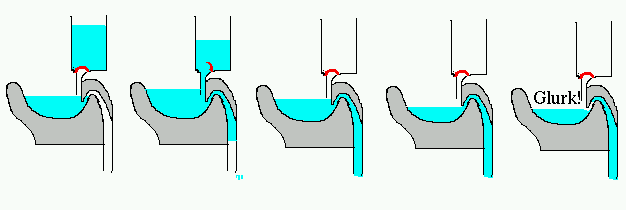
3.Explain what happens when you flush a toilet. We will
assume that the tank starts out filled, and not
consider how it gets refilled later. But we are
interested in all the things that happen to the water
level in the bowl, and why it goes "glurk!" at one
point.
First, the bowl fills up. When the water level gets high enough, it starts
running down the drain pipe. This starts a siphon action, which drains
the bowl -- until the water level gets low enough to let air into the
siphon (which makes the "glurk!" noise).
1.Sometimes switches do more than just connect or disconnect one wire. For example, a common kind of switch is the "double throw" switch which connects the wire on the left to the upper wire on the right or to the lower wire on the right, depending on its position. If you want one light to be controlled by two switches (one at the foot of the stairs, one at the top of the stairs), you could use two of these:
Another kind of switch is the "double pole" switch which really is two separate switches connected so that you turn them on and off together. This would be useful if you wanted to turn on both the stove light and the fan at once.
Finally, there are even "double pole double throw" switches.
Here are some problems you can solve using switches of these kinds:
*A You want a single switch that will turn on a red
light or a green light to warn people when you do not want
to be disturbed. One light or the other should always be on.
*B You want a box that contains a battery, with two wires
coming out -- but which wire is positive and which
is negative can be reversed by flipping a switch.
*C You want a switch that disconnects both wires going to
the light in the back yard when it is off, because
you are afraid a lightning bolt might come into the house on a wire.
*D You want to disconnect your house from the power company
and connect it instead to your emergency
generator (represent the house by one light bulb, and
the power company and your generator by batteries).
*E You want to be able to turn on and off the front yard
light from three different places -- the garage, the
front door, and your bedroom. Flipping any switch causes
the light to go on if it is off, or off if it is on.
Design three of these circuits. For your discussion, explain
what kinds of switches you will use, and then which
connectors are connected to which, using the labelling
scheme in the diagrams.
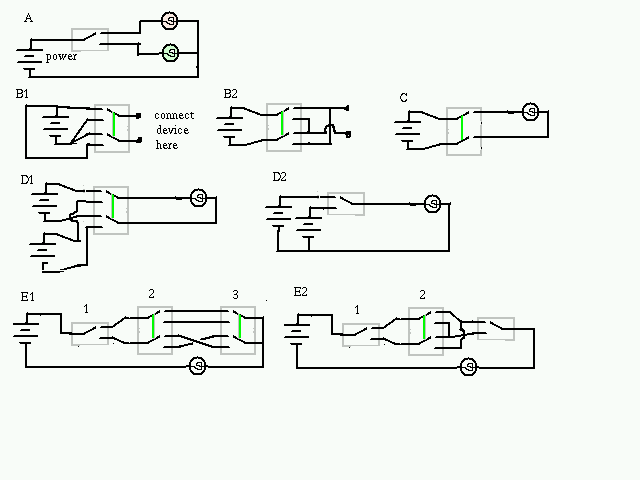
A. A double throw switch, with A connected to one light bulb and B connected to
the other.
B1 . A double pole double throw switch, with the positive end of the battery
connected to A and D, and the negative end connected to B and C. Then X and Y
are connected to the two ends of the battery, and the polarity is reversed when
you throw the switch.
B2.This is actually the same reversing switch, but the battery and
the device have traded places.
C. A double pole switch will let you connect the two terminals
of the light bulb to the two wires from the power company.
D1. A double-pole double-throw switch connects the light bulb to one
power source or the other. This design has the advantage that you are
not connected to the power company at all. This might be a good idea, if
the reason we are using the emergency generator is that a tornado has
knocked down all the power lines: lines may have shorted and it is quite
uncertain what voltage the lines may be.
D2. This is a simpler solution, that only needs a double-throw switch.
This would be the way you switch your radio from a wall-plug power supply to
the battery backup.
E1. This one is pretty complicated! The upper pair of terminals of a
a pair of double pole double throw switches are wired in the usual two-switches-
controlling-one-
device configuration; the lower pair are also wired this way, but with a crossing so
that
these gives a connection from 2Y to 3Y when one switch is up and the other is down.
Finally
a double throw switch chooses one of these circuits. You will see that changing any
switch
turns off the light bulb if it is on, or turns it on if it is off.
E2. This is a simplification of the previous circuit. Since
the X and Y wires of the last double-pole double-throw switch were tied
together in circuit E1, it is the same as a single-pole double-throw
switch.
2.Electrical appliances usually have a little placard on the back or bottom giving their electrical ratings, specifying voltage (V) and either current (A) or wattage (W) (or possibly both). (It also tells the frequency (Hz or cycles); this is of less interest to us at the moment). Please make a table of the information for various devices.
Judging from your table, what are the implications of a device with a very large current rating? Houses have fuses or circuit breakers that act like switches to disconnect any device that is drawing a current that is too large -- for example, more than 15 Amperes. The sum of the current ratings for the devices on a circuit must be less than the circuit breaker's limit.
Here ( http://www.pa.uky.edu/sciworks/em/tabla.htm ) is a table of the various devices that have been reported.
High current devices are high power devices -- things like heaters and devices with large motors in them. Drawing a high current is a signal that a lot of power is being drawn. The circuit breaker limits the amount of current, so that it is also limiting the amount of power. If a circuit starts drawing too much power it might mean that something has gone wrong -- a short circuit, that could cause a fire. The current rating on the device tells you how many things you can put on the same line. The 12.5 Amp heater needs a line all to itself; the computer monitor can share a line with other devices.
One group said:
"
It appears that the larger devices (those that require more circuitry or
do more things or do them more frequently) draw more current through the
system in the same amount of cycles as a smaller device. Implications
could include limiting the number of devices that require a great deal of
current to a single circuit breaker so that you wouldn't be constantly
"tripping your system" by demanding too much current at one time.
Therefore, the kitchen should have more than one switch to control
"overloading" on the breaker that leads to the power company. We also
discussed that we know there is some connection between voltage, amps and
watts. We understand that voltage is the potential energy and amps is the
amount of current flowing a lot like the siphon where the "source" is the
potential energy and the flow rate is the current. We think that there is
a ratio that leads to determining power which is watts. We are just not
sure how to find it, especially since most appliances give W or A but not
both. Perhaps the wattage is given so frequently is because that is what
our bill from the electric company gives us? Oh, we think we found out
connection: watts/current = voltage. Did they not put both because if
you have two parts of the information you can find the other?
"
Joe Straley's comment:
Yes. We haven't talked about voltage yet, so you are ahead of
the syllabus. We will come back to this table later.
1.Electrical systems require a circuit. Is this true of a water system, too, or is the analogy between the systems imperfect? Before we make a final judgment on this, please do the following activity:
Find a plastic bottle with a tightly fitting cap or lid. Fill it with water, and put on the lid. Then punch a small hole somewhere near the bottom with a needle or a tack or a sharp pointed knife, and let the bottle stand for a few seconds. Then remove the lid, and put it back on again (of course, you will do this over a sink, and expect to get wet).
Now please discuss how this water system is like an electrical circuit.
In an electrical circuit, current comes out one end of the battery and must return to the battery. In the water system, water comes out of the bottle, but only if something else goes in -- air. If we include air into our water system, then it resembles the electrical system a bit more: the flow rate of water out of the bottle has to be balanced by the flow rate of air into it.
One group said:
" Water systems also require a circuit of some type, in that there has to
be an energy source for the water flow (such as gravitational potential
energy), a connecting pathway (such as a river bed), and an enegy receiver
(such as an ocean). These are parts that are also required to a circuit.
For the activity part of this question: When the lid was on the
bottle, the only way to get water to squirt out of the hole I made was to
squeeze the bottle. However, when I removed the lid, water came out of the
hole whether I was squeezing the bottle or not. After I replaced the lid,
the water stopped coming out of the hole again (unless I squeezed the
bottle).
This water system is somewhat like an electrical circuit. There must
be a complete pathway from one end of the battery to the other in a circuit-
otherwise, it won't work. In the case of the water system, the only way to
get the water to leave the bottle was if there was air to replace the void
that was created. Or, you could force the water to leave by squeezing the
bottle. Either way there had to be some sort of energy imput and
organization to the system in order for it to work. Putting the lid on the
bottle was analogous to closing the switch on a circuit.
The water system was different from a circuit, however, in that the
water did not travel in a closed pathway. Once the water left the bottle,
it did not go back unless it was collected and poured back into the system.
"
Another group said:
"* Water only flows in one direction just like in a direct current, but
one of the difference is that water does not flow in both directions like in
an alternating current.
* Once the potential energy is gone it is gone and the flow of water
or electrons stops.
* The lid or a dam act like a switch in a circuit.
* They both start running down. When the battery starts to die the
tape of a tape deck sounds drawn out and the water in the plastic container
doesn't shoot out as far and starts to dribble."
All good points. In the context of the little activity I proposed here, you found out that water only runs out when the lid is off. For water to come out, something has to move in. The circuit involves fluids (which includes both air and water), and "heavy fluid" (water) runs out so that "light fluid" (air) can run in.
2.The water supply to a house is easier to compare to an electrical system, because the water stays in the pipes (we hope!), just as the electricity stays in the wires. Another similarity is that we can't see inside the pipes to tell what is going on.
Suppose you found a pipe in your basement, and you wanted to know which way the water goes in this pipe. All you can do is trace where the pipe comes from and where it goes to -- what gets connected. Explain how you would use this information to answer the question.
First find where the water pipe comes into your house. Follow the pipes from there through the various connections. One disappears into the washing machine, another into the water heater, another into the refrigerator (for the ice maker), and some end in faucets and obvious outlets. All of those pipes are readily labelled: water comes from the water company and goes somewhere. There is another pipe coming out of the water heater, which delivers hot water to where it is needed. There is nothing to tell us which way the water is going in the pipe from the hot water heater to the washing machine, until we know the purpose of each, and then it is again clear.
The electrical equivalent to this would be to find a wire somewhere under the hood of your car. Which way does the electrical current go? Again you can trace where the wire comes from and where it goes to. Explain how you would use this information to determine the direction of the current.
Now we start from the positive end of the battery. This is where the current comes from. Eventually the current must return to the battery, but the car people have complicated this part -- the negative terminal of the battery is connected to the car frame. All the metal parts of the car are a wire in the electrical circuit! But this also makes the analysis of the circuit easy, because in general every device is connected to a wire that comes in and to the car frame. The current flows from the wire through the device to the car frame (and then back to the battery).
1.When you made the table of the ratings of various household devices, there were a number of boxes you had to leave empty because either the power or the current rating was not given. But now you can fill in the blanks -- for example, the computer monitor uses 1.8 Amperes x 110 V = 200 Watts.
Why does the household circuit breaker limit the current to 15 Amperes? Why do we need the circuit breaker at all, since none of our devices use this much?
The revised table is here ( http://www.pa.uky.edu/~sciworks/em/tablp.htm )
Filling in the blanks in the table is more than a math exercise, or a reinforcment of the idea that power = current x voltage -- we also get a feel for how much power different devices use. To put the numers into an everyday context, note that 1000 Watts for 1 hour (a kiloWatt-hour) costs about $0.10 (less in Kentucky, where all the coal comes from). So the electricity for your CD player costs less than a dime a day (you will get a separate bill for the window-rattling stereo system that it is connected to); a big batch of southern fried chicken also involves about a dimes worth of electricity.
The current that is going into a circuit tells us how much power is being used in it. One way to get too much power is to have a short circuit, that could lead to a fire. A circuit that is drawing a very large current should be turned off quickly, and that is one thing that the circuit breaker does for us. But what is wrong with plugging in the space heater and the hair dryer and the microwave into the same circuit? The large current in the wires might make them warm, which could also lead to a fire. The circuits were designed to carry a certain amount of power; the circuit breaker keeps us from exceeding the expected value.
My first electrical experiment, at age 4, was to attempt to unplug a lamp with the aid of a table knife. If I had succeeded in the original plan, I would have sawed the prongs off of the plug. Fortunately, the knife had a nonmetal handle, I wasn't grounded, and the fuse turned off the experiment -- but there was a shower of sparks and two notches burned into the blade of the knife.
The knife handle, the fact that there was no circuit through me, and the fuse all helped prevent having an electrical current go through me, The current would have been bad, because it would confuse the nerves: it would surely hurt a lot, and might have caused my heart to beat at the wrong time.
2.The battery you made was several simple batteries in series. Use energy concepts
to explain why this makes a
higher voltage battery.
In the battery you made, the wet parts were aways above a zinc-coated washer
and below a brass washer. What
goes wrong if we also get the surface above a brass washer and below a zinc-
coated washer wetted with the
vinegar solution?
As the current flows, chemical reactions take place that release energy. Each zinc atom that leaves the metallic state and becomes a zinc ion gives rise to two electrons that move in the circuit. When the batteries are in series, the same current causes chemical reactions in each cell (technically, one pair of plates is a cell, and only a combination of cells is a battery. But the language has eroded). Three cells in series are releasing three times as much energy when the same current is flowing. The way the external circuit finds out that there is more energy available is that the voltage is higher - there is more pushing the current.
The single cell consists of a zinc washer and a brass washer, slightly
separated and then connected by the layer of salty vinegar.
The positive end is the brass washer.
If you get the wrong junctions wet, you will have introduced a backwards cell
into the circuit: for example
Zn-wet-Brass-wet-Zn-wet-Brass
contains three cells (Zn-wet-Brass)(Brass-wet-Zn)(Zn-wet-Brass)
and the middle one is pointing the opposite way of the other two.
As the current flows, the
chemical reactions will take place backwards, and this cell is being recharged
instead of discharged. But that decreases the
voltage of the assembly.
3.Some batteries are rechargeable (for example, the one in your car). How is a rechargeable battery similar to a capacitor, and how is it different -- of course they are different inside, but what differences in behavior are there?
From the outside a capacitor and a rechargeable battery are rather similar. Inside, a battery is doing chemistry, while the capacitor is doing physics. The capacitor cannot store very much energy (a few Joules, at the most), while a battery is good for thousands of joules. However, a capacitor can give up all of its energy in a very short time, while even a short-circuited battery will last for a while, because there is a traffic jam at the surfaces where the reactions are taking place. Batteries tend to maintain a nearly constant voltage until they discharge, while a capacitor's voltage decreases in proportion to the amount of energy that is left. The capacitors in the kit were originally intended to go in a computer, to keep the circuits alive if there was a brief power outage.
4.If your car has a dead battery, perhaps someone has jumper cables and can help you get the car started. The instructions say to connect the plus terminal of one battery to the plus terminal of the other battery, and then connect the car frame of one car to the car frame of the other car (this is equivalent to connecting the negative terminals, but puts you farther away from the battery -- just in case something goes wrong). Explain why this is the right thing to do, both from the point of view of the dead battery and from the point of view of your nonfunctioning car.
The question is, why not connect plus-to-minus (like you do in a flashlight)?
First consider what the starter motor sees. A particular wire
from the starter motor is connected to the plus terminal of the dead battery; we
should connect the good battery so that the
starter motor is connected to the plus terminal of it - or the starter motor
might try to turn in the wrong direction, which surely
isn't good for the motor (all the valves and stuff would open and close at the
wrong time). In the picture below, the current is flowing the
right way, since the batteries have been connected correctly.

With the two batteries connected this way, current flows "backwards" in the dead battery -- current goes in the positive terminal. This causes the chemical reactions in the battery to happen backwards, which stores energy. The battery is being recharged, so that you will be able to start the car next time you need it.
Connecting the positive of each battery to the negative of the other would give a short circuit, in which there was nothing to prevent an enormous current from running through the jumper cables. A car battery is capable of delivering hundreds of amperes, which would surely get the cables red hot.
There are two ways to connect two batteries together (and not ruin something):
in series or "in parallel"
When we place the batteries in series, the same current makes chemical reactions
take place in both batteries, so energy is released twice as fast. The result is a higher
voltage. Placing them in parallel means that half of the current goes through each
battery. The energy released by the chemical reactions per electron that goes
through
is the same, so the voltage of the cmbination is still 1.5 V, but the batteries are being
discharged half as fast (as a single battery would be). So the combination will run
the circuit twice as long as a single battery.
1.You can buy light bulbs intended for 115 V with a wide range of wattages -- 5 W for little nightlights up to 250 W and more for lights intended to illuminate the whole back yard. Which kind uses the most current? Which kind has the highest electrical resistance?
One group said:
"Power = voltage x current
5w = 115 v x I
I = .043 amps
250w = 115 v x I
I = 2.17 amps
The 250-watt light requires a current of 2.17 amps where the 5-watt
bulb only requires a current of
0.043 amps. The 5 watt bulb has the highest resistance because
resistance is the ratio of voltage to
current therefore the resistance of the 5 watt bulb is 2674 ohms while
the resistance of the 250 watt
bulb is 53 ohms thus it has the lowest resistance.
Voltage = current x resistance
R = voltage/current
R = 115v/.043 amps
R = 2674 ohms
R = 115v/2.17amps
R= 53 ohms
The resistance determines the current.
Something that requires a lot of current has low
resistance because you want the
current to go through. Like in a siphon: if you have lots of
resistance then you have low current. If
you have a very skinny long tube then you have high resistance but low
flow rate. If you start with 1
gallon of water and have a short fat tube then the water will drain
quickly, but if you have a gallon of
water with a long skinny tube then the water will drain slowly. JUST
LIKE in a circuit. This is why
the light bulb (low resistance) went out quick with the capacitor and
the diode took a long time
because in has high resistance. This is why the diode would light
with really poor conductors, like
orange juice, and the light bulb did not because it needed too much
current. But the light bulb did
work well with the spoon, good conductor which allows current to flow
easily.
"
Joe comments:
This result, that high power corresponds to low resistance, may
seem backwards -- shouldn't there be more energy loss when the resistance
is high? The difference in the two points of view comes from forgetting
what is being held constant. If we had a guaranteed 1 Ampere current,
then the higher the resistance, the greater the voltage drop across the
device and the higher would be the power converted from electrical form
to heat (or some other form). But we usually apply a fixed voltage to
devices, and now a higher resistance decreases the current and power.
2. Is it safe to combine ordinary 115 V light bulbs with the materials in the kit? What would happen if we connect a 40 W light bulb from the grocery store to a battery?
It's safe. The 40 W light bulb wouldn't do anything at all when connected to a 1.5 V battery.
When connected to 115 V, a 40 W light bulb is drawing a current of 40 W/115 V = 0.348 Amps, and then the resistance is 115 V/0.348 Amps = 330 ohms. This is the resistance of the filament when it is hot; it would be somewhat less when it is cold. But we can estimate that connected to a 1.5 V battery we would get a current of 1.5 V/330 ohm = 0.0045 Amp, and then a power output of 0.0045 Amp x 1.5 V = 0.007 W. That's really tiny -- there would be no visible glow, and in fact the filament would not get perceptibly warmer.
3.You are shopping for a new light bulb for your desk lamp, and the salesperson offers you the choice between a 100 W incandescent bulb and a 25 W compact fluorescent bulb. Is it good or bad that the wattage of the compact fluorescent is smaller? The salesperson claims they are equally good for lighting -- how can this be true? To really compare the two, we should note that the compact fluorescent bulb costs $8, while the incandescent bulb only costs $1; they both are expected to give light for 10,000 hours. Does this difference in initial cost matter very much to the decision?
An incandescent light bulb makes light by getting a little wire really hot -- over 2500 o C! But in addition to making visible light, it makes a lot of invisible infrared light, which we can perceive as heat. An incandescent light bulb is a much better heater than light source. Fluorescent light bulbs make more visible light from the same amount of power -- which is why almost all commercial and public buildings are illuminated with fluorescent lights. We are used to quoting the power usage of a light bulb as a way of indicating the amount of light put out, but we can't compare light sources of different kinds this way.
The cost of electricity is about $0.10 per kilowatt hour. In 10,000 hours, a 100 W incandescent light bulb will use 1000 kwhr at at cost of $100; the fluorescent light bulb will only use a fourth of this, and only cost you $25. Buying the cheaper light source is not the right way to save money!
4.In your kit you will find a small piece of thermal sensing sheet. It is a kind of thermometer, that is probably black at room temperature but will turn green or blue when you touch it (or if it is rather warm in the room). When you are through playing with it, let it cool back to a uniform color. Meanwhile, cut a piece of aluminum foil that is 1/2 cm wide and 10 cm long. Straight is OK, but it is more fun if it is somewhat curvey. We are going to use this as a wire. Place the thermal sensing sheet on top of the aluminum foil wire, so that the two ends of the wire stick out. Attach wires with clip ends to the battery, and then to the ends of the aluminum foil. Explain what happens.
The aluminum foil wire becomes a heater, as is revealed by the thermal sensing sheet. If you make the wire wider some places than others, you will probably observe that more heating happens at the narrow places. Just as the speed of a river has to be higher where the cross section is smaller, the average speed of the electrons is higher in the narrow places. This means more energy is turned to heat in these regions. And since the regions are smaller, the heating is more concentrated.
What's wrong here?
A: The light bulb is in parallel with a wire. If there is any voltage
difference from one side of the light bulb to the other, it will cause a
large current to flow through the wire, releasing a large amount of power.
There is a limit on the rate which a battery can supply power, however,
so we conclude that the voltage across the light bulb will be small and
that nothing will seem to be happening -- but the battery won't last very
long.
B: Oops, no battery. Without an input of power, there will be no power
coming out, either.
C: The two batteries are in opposition. The current can't figure out
which way to go. If a current were to flow clockwise, the battery at the
left would be delivering power to the circuit, but the battery at the
right would be absorbing it (the battery would be charging up, if this
is possible). There is no energy left over to make light in the light
bulbs, so again nothing happens. This circuit might be useful if you
wanted to have two rechargeable batteries that were at exactly the same
voltage -- they would come into equilibrium after a while.
D: The circuit running around the outside has two batteries delivering
energy, and very little resistance. This would run down the batteries
quickly, and make the wires hot. There is no reason for current to go
through the light bulb, and so it would not be on.
E: Although there are some circuits here, the battery is not in a
circuit. Any current that were to go through it would have no way to
get back. So nothing happens.
F: We have connected the light bulb to 6 V but it is only designed
for 3 V. The current will be twice as large as usual, with twice the
voltage pushing it, so the light bulb will be four times as bright as
usual -- until the filament melts, which will only take a fraction of
a second.
2.If we wanted an indicator light to tell whether the toaster is on, we could use a parallel circuit or a series circuit. What are the advantages of each design?
Neither design seems quite satisfactory.
* Having
them parallel is simplest, but if the toaster wire breaks, the
indicator light will still claim toast is being made; if the
indicator light burns out, it will fail to warn you when the
toaster is on.
*In a series circuit, the toaster stops working if the indicator light burns out --
which might be a good idea, if you regard the light to be
necessary for safe operation of the toaster.
However, we
have to get a special light bulb. The toaster is an 800 Watt device,
which draws about 7 Amperes; the usual light bulbs designed for 115 V
would limit the current to much less than this. We could make a light
bulb that emits 1 watt when 7 Amperes flow through it (the resistance of this
light bulb is very low), but there is
still a problem: the toaster wires have a lower
resistance when they are cool; the current surge when you
just start toasting might burn out the light bulb.
By the time you get this special light bulb, you will discover that
you might as well have cut a little window so that you could see the
toaster wires.
One group said:
"
If you want the indicator light to actually
indicate whether or
not the toaster is on, you would want the light and the
heater to be in a
series. Otherwise, the light could be off while the
heater is on! On the
other hand, though, if the heater is like the light bulb
in our kit and the
indicator light is like the buzzer in our kit, only the
indicator light
would work because it requires less current. Since the
heater would require
more current (I'm assuming), it wouldn't work unless
the light also needed
at least the same amount of current. Also, if the
indicator light were to
malfunction, the heater would not work until you
replaced the light because
they are in series. This is an advantage of a parallel
circuit- if one item
malfunctions, the rest may still work.
"
1.Make a map of the field for one of the round magnets from the kit, lying on one circular face. Explain what you see.
When I try to map the field of a circular magnet lying on its face, I find that
close to the magnet
the compass doesn't work -- it won't turn freely, and when I tap on it it will reorient
to make a picture
like you have drawn. Farther away -- more than 6 inches -- it doesn't seem to
notice the magnet at all. 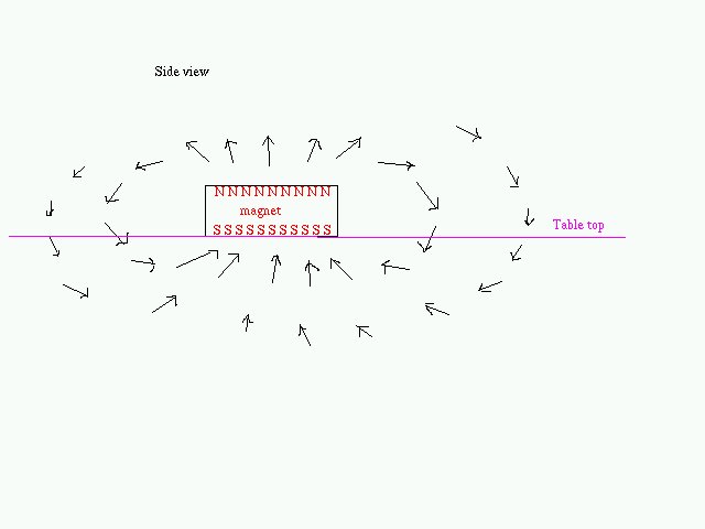 The reason for both of these observations is that the magnetic field due to the
magnet is mainly
up and down. The needle can't turn this way,
and jams against
the cover when it tries. Farther away, the compass responds to the earth's
magnetic field and
ignores the vertical part.
The compass is designed to ignore the vertical part, or we would find out something
else about Kentucky --
the magnetic field is almost vertical here!
The reason for both of these observations is that the magnetic field due to the
magnet is mainly
up and down. The needle can't turn this way,
and jams against
the cover when it tries. Farther away, the compass responds to the earth's
magnetic field and
ignores the vertical part.
The compass is designed to ignore the vertical part, or we would find out something
else about Kentucky --
the magnetic field is almost vertical here!
One group said:
It is difficult to make a field map for this type of situation since one pole is lying flat against the paper and the other pole is on the top. The arrows would have to be sticking out of the paper, which isn't possible when using 2-D drawing methods. Turning the magnet on its side would make it easier to map the field- one side would have arrows pointing towards the magnet, while the other side would show the arrows pointing away fro the magnet.
The compass can only see the part of the field that is horizontal (if we ignore any tilt of the needle). Because the compass is not exactly in the midplane of the magnet, it will see something, especially close to the magnet.
2.Make a map of the field of a bar magnet that has three large paper clips attached to it, reaching from one pole to the other. Do the paper clips alter the field or only react to it?
The change is not large, but the magnetic field of the bar magnet is measurably less. For example, if you place the bar magnet north of the compass but pointing the wrong way, you will find that close to the bar magnet the compass points away from the bar magnet (south) while farther away it points north, and there is an intermediate region where it isn't quite sure which way to point and will let anything else that is magnetic be the tie-breaker. The big paper clips decrease the field strength, so that the earth's field wins closer to the bar magnet.
One way to explain why iron is attracted to magnets is that the energy of the magnetic field is lower when it is inside iron. Then when you put paper clips on the magnet, arranged pole-to-pole, it makes a kind of "short circuit" where most of the field stays in the paper clips and only a little bit spreads out around the magnet.
The inside story about iron is that on the small scale it is always magnetized, for reasons that have nothing to do with magnetism, but different regions have their magnets pointing different directions. An external magnet will realign these, either temporarily (while the iron is sticking to the magnet) or even permanently. The extent to which this realignment occurs and survives when the magnet is removed can be designed in by choice of material and how it has been treated. Paper clips become modest magnets -- good enough to use as a compass (just hang it from a thread so that the long direction is horizontal).
3.Have one member of the group hide several paper clips under a magazine. Then have other members of the group find them. How can you tell which way the paper clips are pointing? (Note: this will not work on a steel desk top!).
Trying to find the paper clips by holding a magnet and waving it around doesn't work very well, because the force on the magnet is small until it gets really close to the paper clip. However, if you dangle the magnet from a long string, the small force will cause the string to deflect to one side, revealing the paper clip's position; and if the magnet can also twist the string, it will probably line up somehow with the axis of the paper clip. A little experimentation with a paper clip that you can see will show you what to expect from the hidden ones.
Another strategy is to use a compass. Since this is also a magnet, it isn't terribly different from the first strategy, but I suspect one method works better than the other. 4.There are many ways to put two bar magnets into a package that is 4 cm x 5 cm. Suppose someone gave you one of these packages -- how could you find out which one it was? (You could make one of the packages to test. Cut pieces of heavy corrugated cardboard to make the gray parts, tape the parts together, and then wrap prettily).
The compass N will point at the S end of the bar magnets in the package, when it is close to the package. The field maps for these various combinations are quite distinct, but you have to be a good observer or you will miss the twice-as- strong N pole in diagram C and the very rapid change in direction of the field where the N end of one magnet meets the S end of another in diagram B. Magnets
1.If we cut a long bar magnet in two, to make two shorter ones, will the pieces want to stay together or fly apart? If we break one of the flat black magnets as shown, will the pieces want to stay together or fly apart?
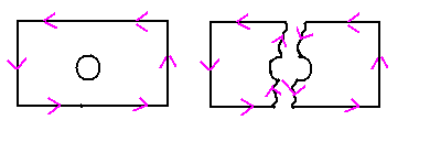 Everybody seems to know the answer to the first one, and
too many people generalize this to a rule that magnets want to stick
together. But the top surface of the flat magnet is one pole and
the bottom surface is another; these will not want to remain side by
side.
Everybody seems to know the answer to the first one, and
too many people generalize this to a rule that magnets want to stick
together. But the top surface of the flat magnet is one pole and
the bottom surface is another; these will not want to remain side by
side.
An implication of this is that magnets would like to turn into
something else. Suppose a magnet were made of something that
could change shape, like molasses. It would
turn into something very strange -- I'm not
even sure what! Perhaps a flat ribbon with N on one side and S on the
other (and then the ribbon would roll up into a coil, to get the N and S
together). If the magnet were made of stuff that was easy to break, I
think it would fly into pieces which would then reassemble into a
collection of grains of alternate orientation -- it wouldn't be useful as
a magnet any more.
This is why natural iron is not very magnetic, even though it is made of small domains that are all magnets: the energy is lower if the domains point different directions. We can force them to point the same way by putting them in a magnetic field (even the earth's field will start the process, which is why we have lodestodes), but they will lose their magnetization over time, especially if they are knocked about.
One group said:
For the bar magnet, the pieces should want to stay together.
Because of the way the domains align within a permanent magnet, the
one
whole magnet will make two smaller magnets when broken, each with a
north
and south pole. In the place where it is broken, the right side of one
piece will become the north pole of that new magnet and the left side of
the
other piece will become the south pole of the other new magnet.
Therefore,
when these pieces are brought back together, they will attract.
As for the flat magnet shown in the picture, when it is broken,
those pieces will repel if the north and south poles are on the long, flat
sides of the magnet because, after they are broken, the two pieces that
were once the north pole will become two north poles. When brought
together,
they will now repel one another. However, if the north and south poles
are
on the ends (in other words on the left and right as shown in the picture),
the outcome will be similar to that of breaking the bar magnet.
2.Give examples of how magnets are used around the house, at school, in your car. Using your compass, try to determine where the poles are for some of the magnets.
One group said:
There are lots of magnets in my house. There is one inside
my refrigerator door to help keep it closed. There are also some on the
outside of it to hold pictures and notes.
At school, there are magnets in the hand generators my
students use to turn mechanical energy into electrical energy. There are
magnets holding papers on my whiteboard. There are the magnets and
compasses that I use to teach magnetism. And, there is a model of the
atom
hanging on my wall that comes with magnetic protons, neutrons, and
electrons.
Some of the magnets had poles similar to the flat rubberized magnet we looked at. Others were donut magnets with the poles on the top and bottom flat sides or bar magnets with the north and south poles at either long end.
atom hanging on my wall that comes with magnetic protons, neutrons, and electrons.
Some of the magnets had poles similar to the flat rubberized magnet we looked at. Others were donut magnets with the poles on the top and bottom flat sides or bar magnets with the north and south poles at either long end.
3.We have been describing magnets and how they interact in terms of their poles. However, there is another way to describe them, in which we draw arrows on the sides of the magnet instead of poles on the ends. The arrows run around the magnet, so that when you view the magnet from one pole end, they describe a one-way path around the magnet.
Decorate some of your magnets with arrows like these, and then observe how they account for the interaction of magnets, for the various cases that the magnets are end-to-end or side-by-side: what are the arrows doing when the magnets are attracting, and what are they doing when the magnets are repelling? How could you use the "arrow" description to explain the behavior of the broken magnet shown above?
The two descriptions -- arrows running around the magnet or poles on the ends -- are alternate ways to describe magnetism. The "arrows" description has one point in its favor: it is impossible to have a magnet with only one pole (the poles of a magnet are the parts on the surface which are enclosed by a circle of arrows, as you explain); the appearance of new poles on the new ends of a broken bar magnet seems quite natural and inevitable. On the other hand, when we break the flat magnet, we have to explain how new sets of arrows appear on the broken magnet. When you use the "arrow" construction on an electromagnet, the arrows point in the direction of the current in the wires. So the arrows are somehow related to current.
One group said:
When using the arrows, we found that when the arrows both point in the
same direction or match up they attract to each other. However, if you
match up the arrows going in the opposite directions then the magnets
repell away from each other.
We put tape around the round magnet and drew the arrows. The tape had to go around the side because the poles are on the faces of the magnet. When the North pole is facing up (and you are looking down on the magnet) the arrows rotate counter-clockwise. When the South poleis facing up (and you are looking down on the magnet) the arrows rotate clockwise.
1.We have many motors around the house that are plugged into the wall socket which provides alternating current. Explain why the kind of motor you made will not work with alternating current. (Do not try to use 110V AC from the wall socket with your motor!! The voltage is too high, and your motor will turn red hot and melt! The question assumes we have used a transformer to produce 3V AC).
There are three ways to use alternating current to run a
motor:
* 1.You can convert the AC into DC, using a circuit
element that will only allow current to flow one way.
Then you can use a motor like the one you built. This
is what is done in low-power devices such as electric
toothbrushes.
* 2.You can have a permanent magnet rotating in the field
of an electromagnet driving by AC. Since the field
keeps on changing direction, the permanent magnet
has to keep on rotating. This is the kind of motor in
clocks.
* 3.You can have an electromagnet that rotates in the field
of a stationary electromagnet. The design would be just
like the motor you made, except that the permanent
magnet would be replaced by an electromagnet. This is
the kind of motor that is used in larger appliances.
Discuss the advantages and disadvantages of these different designs. Why can't we use the second kind of motor for everything? How does the third kind of motor avoid the problems caused by having alternating current?
One group said:
The motor we made will only work with direct current because the coil of wire
acts like a magnet. The wire turns a half turn because of the interaction
between the coil of wire and the magnet. The current will stop briefly,
making the coil turn another half turn. This continues until the circuit is
broken. If alternating current were used, the coil of wire would be unable
to turn properly. The coil would change the direction of its magnetic field
120 times a second, and would be alternatedly pushed and pulled at this
rate. The coil would not turn -- at most it would vibrate in place, making
a low hum.
The advantage of the first design is that you can continue using power from the main AC circuit. It would still be included on your one electricity bill and you can power a smaller motor like the one in the toothbrush. However, you need the conversion device.
The advantage of the second motor is that, in the case of the clock, a rhythmic, predictable cycle is created as the permanent magnet rotates in the field of the electromagnet. This design requires that the rotor turn at exactly the rate of the ac. This is good, for a clock -- if the ac is accurate (and for this and other reasons it is extremely accurate), the clock will keep correct time. This design is sometimes used for other devices which are supposed to turn at a particular rate, but they are not very good if there is a load -- if theyare supposed to deliver power. Then they have trouble keeping up with the beat.
In the third design, the two coils change field rapidly, but they fields change together so that the movable coil continues to be pushed the same way. Electromagnets convert some of the electrical energy into heat (because there is electrical resistance), and so a motor with two coils will be a little less efficient that a motor with one coil. But a well-designed electrical motor is very efficient, so this is not a big problem.
2.When the water has been off for a while (while the plumber figures out why your dishwasher isn't working), you have to be careful when you turn the water back on: the faucet will cough and suddenly spray water all over the room very violently. This is due to having air in the pipes. But how does that cause these explosions?
While the water is off, air gets in because people turn the faucets on while the water is off, draining water but letting in air. When air is coming out of the faucet (after the water pressure is turned back on, it gets out very easily -- there is not much friction to slow it. So the water in the line behind the air travels faster and faster, gaining energy because the pressure is pushing with water without any opposition. But when the water arrives at the faucet, it is like a hammer hitting the wall. The water has to slow down and this requires an enormous pressure at the faucet. Bang! Squirt! And if there are several bubbles in the line, the faucet "coughs" at you.
The electrical analog of this is the high voltage that occurs when you disconnect a magnet. The energy stored in the magnet field is delivered all at once to keep the current going, despite any obstacle. The analogy is not perfect, but it is relevant.
3.You don't usually observe sparks or get a shock from a flashlight battery. But you will see little blue sparks if you look carefully at certain kinds of electrical equipment -- doorbells and motors, for example -- and you can give yourself a small shock (just a tingle, really) while playing with an electromagnet. Explain how to make this happen (or how to avoid it!).
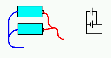
Here is a picture of the situation that gives rise to the shock:
 While you are holding the two wires to
the battery you don't get a shock, because the current goes in the wires (and because
a battery can't make a large enough current flow in your high-resistance fingers).
But when you break the circuit (I erased the battery, but all I meant is that it
is no longer part of the circuit), now the energy stored in the electromagnet has
to go somewhere, and it will insist that the current continue to flow -- through
your fingers if necessary!
While you are holding the two wires to
the battery you don't get a shock, because the current goes in the wires (and because
a battery can't make a large enough current flow in your high-resistance fingers).
But when you break the circuit (I erased the battery, but all I meant is that it
is no longer part of the circuit), now the energy stored in the electromagnet has
to go somewhere, and it will insist that the current continue to flow -- through
your fingers if necessary!
One group said:
Electromagnets will still have a magnetic field even after the circuit
is opened. The stored energy in the electromagnet doesn't just disappear so
if we stick our finger on the electromagnet then we could complete the
circuit and could get a jolt of current. Or we could just let the
electromagnet's energy dissipate or drain the circuit with a resistor of
some sort.
Yes, that's how it works. I have a doorbell that I like to show to kids (they enjoy it because it makes a lot of noise). There is a picture of it on the page "Why study electromagnetism?" The clapper is attracted by an electromagnet, but when the clapper moves towards the bell, this breaks the circuit, so that the clapper eventually returns to the original position. When the bell is running, there is a little blue spark where the circuit is opening and closing. And kids regularly poke their fingers into the mechanism, and are suprised to get a strong tingle in their fingers.