Table of Contents
Related Pages
Beam Monitor
To monitor the neutron flux in the NPDGamma, n3He and other future experiments at the FnPB a pair of beam monitors were required. The first beam monitor prototype used a monolithic macor frame but it eventually failed a few months after construction developing an excessively high leakage current between the signal and HV frames during testing and was disassembled.A new design was made to separate the frames and to provide a drains to ground for leakage current at the contacts points between the frames. These frames were made using PEEK plastic for the frame body. Two were assembled, test and installed at the FnPB beamline for use with present and future experiments. These are generally referred to as the M1 and M2 monitors. A third monitor, M4, is also present but of a different design.
Beam Monitor Operation
The beam monitors are multiwire ionization chambers. When ionization occurs in the chamber the outer two HV frames held at a negative bias voltage relative to the grounded signal plane will cause the positive ions to travel towards the HV wires and the negative electrons to travel towards the grounded signal wires.He-3 neutron monitors operate by capturing neutrons on the He-3 gas that will then break up into a proton and a triton. While the neutral neutrons do not ionize a gas as they pass through a proton and triton will. The ionization from the proton and triton is then what is readout through the preamp to measure the neutron flux through the monitors.
Beam Monitor Construction
CAD Drawings
Dimensions are in inches unless otherwise specified.Critical dimension are:
- Frame have 5.512" x 4.724" interior opening.
- HV wires are 0.5" from signal wires.
- HV wire planes are 1" apart
- 0.2" between wires in a plane
- Wire are 0.205in or 0.132in from inside of window depending on side.
- Interior of monitor is 8" diameter cylinder 1.337" deep.
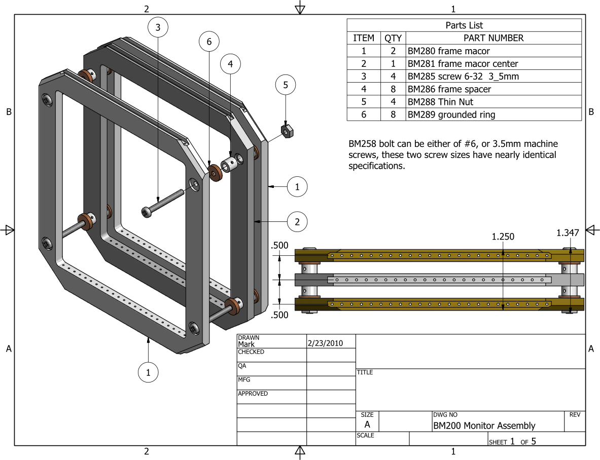
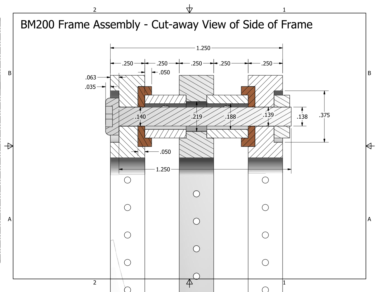
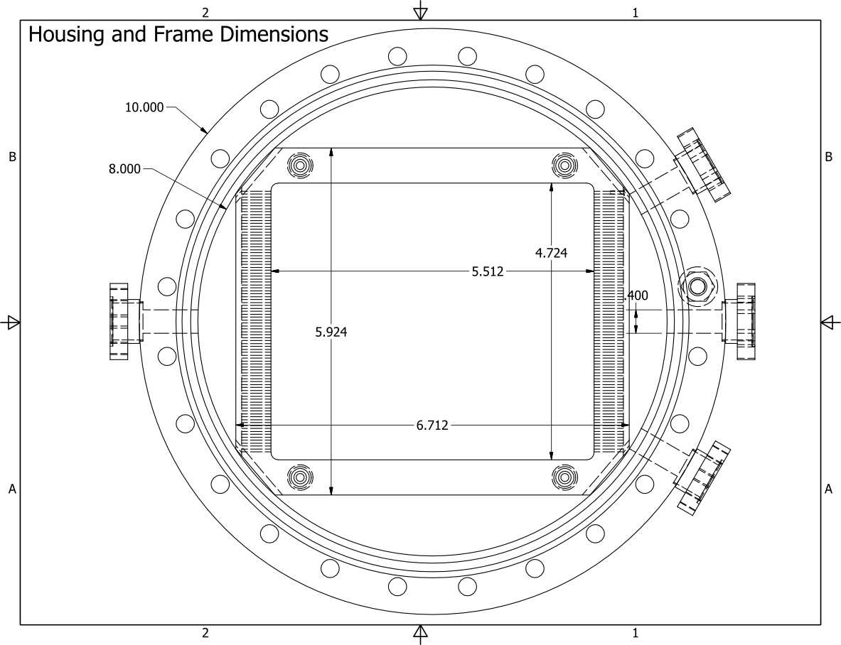
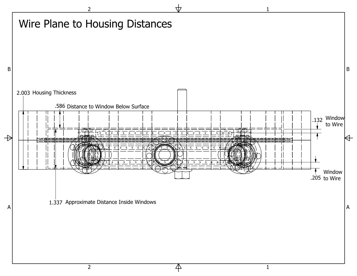
CAD Files
See these PDF's for more drawing details and higher quality images of the above drawings.Assembly Drawings:
BM200 Monitor Assembly.pdf
Wire Frame Drawings (Frames were constructed from PEEK plastic not macor ceramic in the final design.)
BM280 frame macor.pdfBM281 frame macor center.pdf
Spacers and Hardware:
BM286 frame spacer.pdf
STEP Fiile for use in Modeling:
BM200 Monitor Assembly.stp
Autodesk Inventor 2014 SP1 CAD Files:
BM200Files.zip
Autodesk Inventor is the original format for these files.
Construction Images
 |
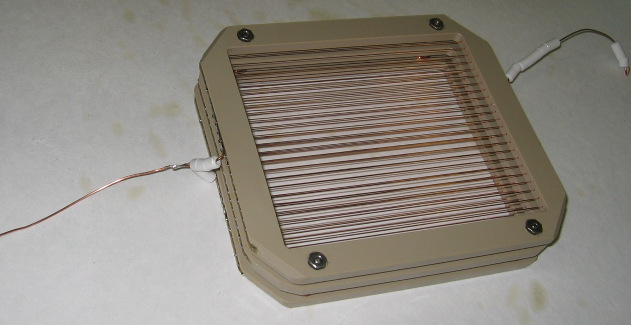
| Three beam monitor frames laid out on a table after soldering. Red plastic insulated wires were replaced with bare ceramic bead insulated wires in the final assembly to control for outgassing. |
 |
| Frame Stack Assembled Outside of Housing. Two copper wires join to the frame stack. The left hand wire will connect the HV planes to the feed thru, and the right hand wire connects the signal wires to the feed through. All signal wires are ganged together in this monitor. |
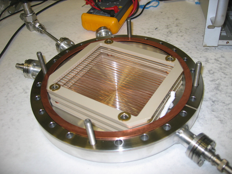 |
| Here the wire frames are in one half of the housing and the copper wires to connect to the feed thrus are fully covered in insulating beads. Around the 4 bolts that hold the frame stack together a split brass washer is used to help hold the framestack in place and will be connected to the drain rings between the HV and signal frames. |
Fill Gas
| Fill Gas |
M1 |
M2 |
| He-3 (torr) |
14.8 |
10 |
| N2 (torr) |
736.8 |
766.9 |
Proton Beam Power Scan
To check the linearity of the beam monitors in response to changing neutron fluxes the average beam monitor signal from each time bin over 800 pulses was compared with proton beam current from the SNS stored data. This was done over a range of 400-800kW beam powers, and it was found to be fairly linear in response over the period of a few months.More detail to be posted.
M2 Calibration
M2 was calibrated at chopped reactor source using the provided calibrated counting monitor. This was then compared with a boron plate scan that was done using the NPDGamma CsI detectors as a comparison.More details to be posted.
Beam Monitor Voltage Scan
For the two He-3 beam monitors on FNPB beam line it is desired to have an absolute wave length dependent calibration of the monitors that will allow a given output voltage to be converted in to a neutron flux. One of the complicating factors in the calibration is that depending on the applied voltage for the beam monitors the portion of the ionization electrons produced in the chamber that are collected will vary.For these beam monitors it is desired to work in the proportional range without amplification. See the wikipedia article on Ionization Chamber and the detector voltage regions imagefor more information. He-3 monitors use He-3 gas in the chamber to make it sensitive to neutrons and then look at the ionization from the beam monitor
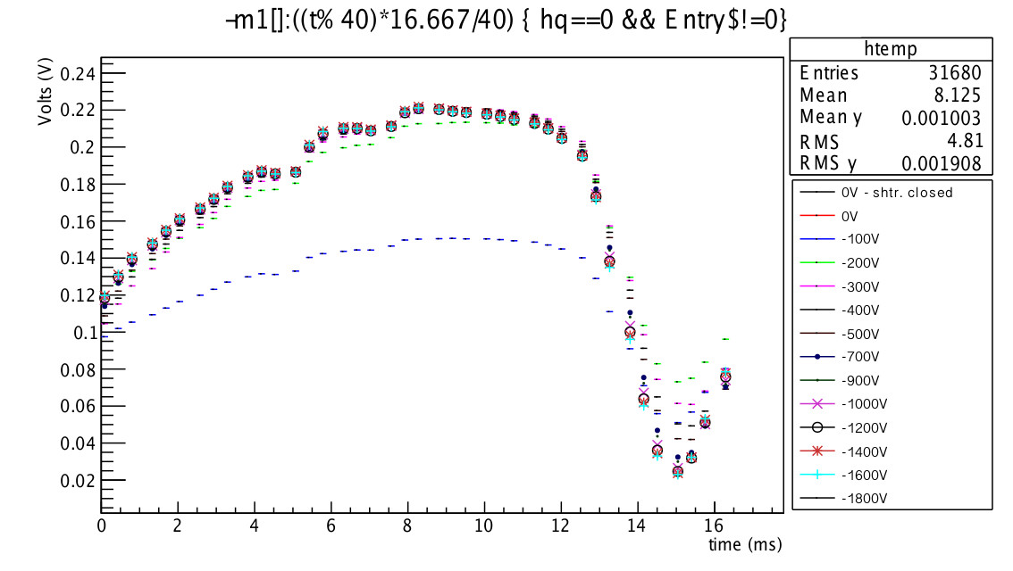 |
| M1 pulse shape on at each bias voltage level. |
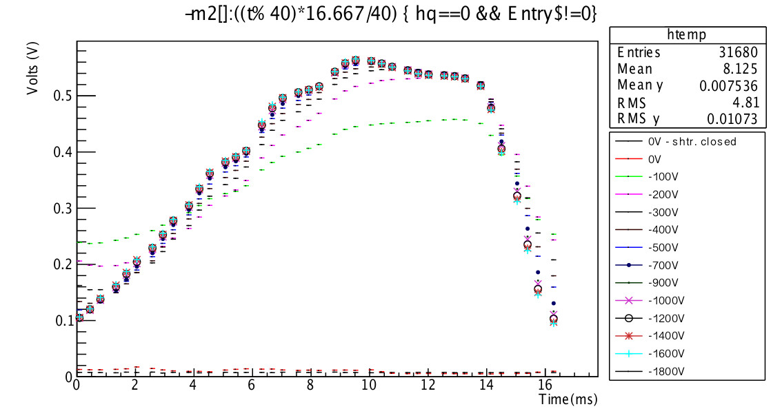 |
| M2 pulse shape on at each bias voltage level. |
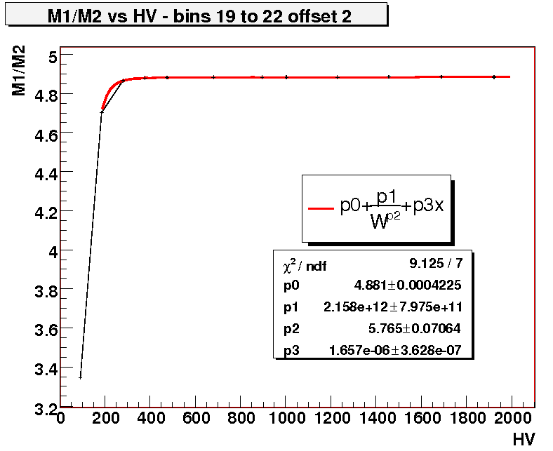 |
| Average M1 monitor signal over 800 pulses (100 8 pulse trains) from time bins 19-22 in each pulse plotted against the bias voltage. To control for beam variations the M1 average was divided by the M2 average over a similar bin range with M2's bias voltage held constant.. |
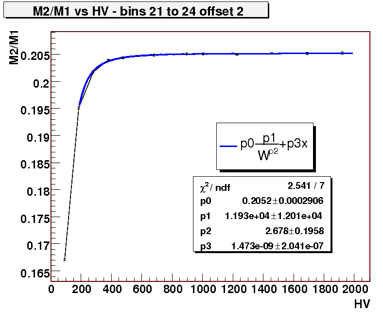 |
| Average M2 monitor signal over 800 pulses (100 8 pulse trains) from time bins 21-24 in each pulse plotted against the bias voltage. To control for beam variations the M2 average was divided by the M1 average over a similar bin range with M1's bias voltage held constant. |