Related Pages:
Table of Contents
Pin Out Board to Feed Thru Pin List
n3He-targetchamberwiring-WiretoPintoADC r4.pdfThis pdf has the full information for the wire chamber to flange to preamp board to ADC for mapping the wire to the ADC channel for readout of the wire chamber.
Wiring Layout
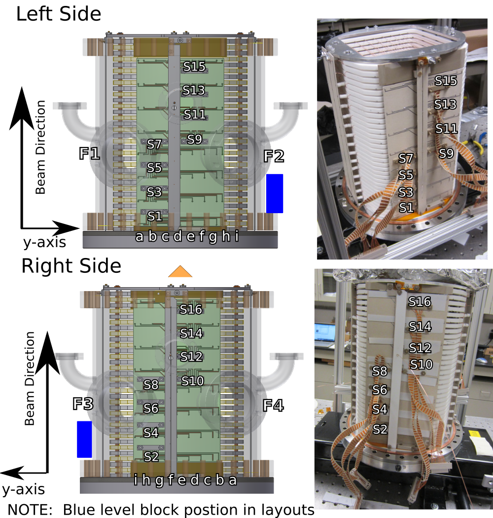
Frame to Feed Thru
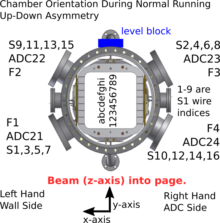
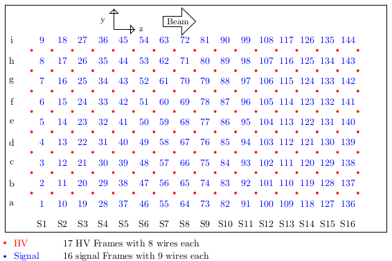
Wire Layout Inside Chamber:
ADC to Chamber Position
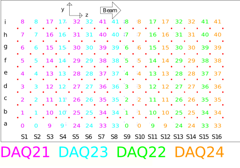
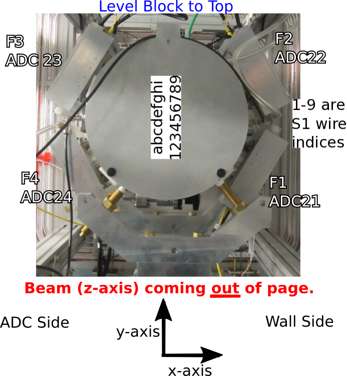
Chamber Orientation in Beam
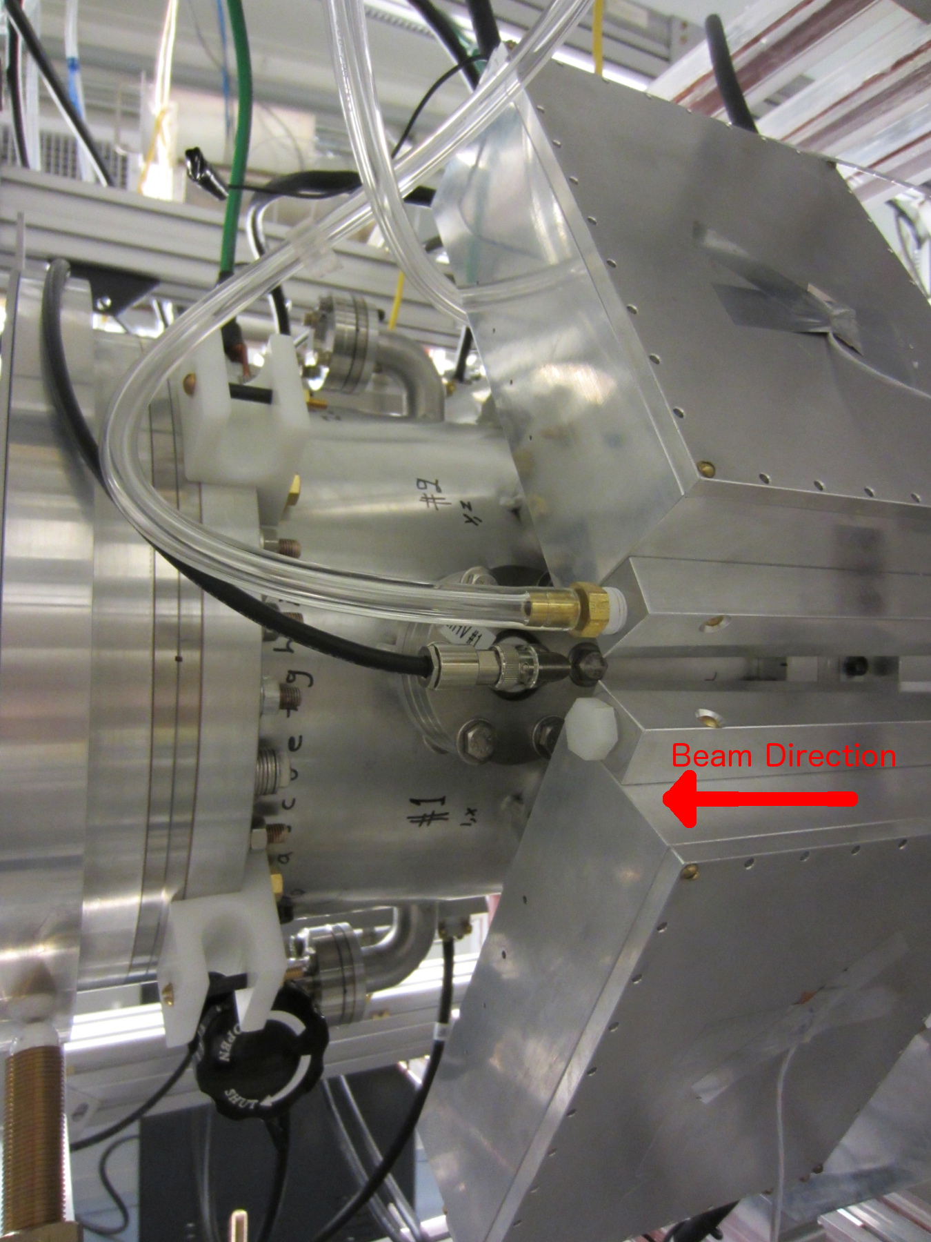
The gas fill valve on the chamber is visible at the bottom of the image, the angle block is then on the top side not visible behind the preamp boxes.
#1 and #2 label the F1 and F2 flanges respectively.
The a-i wire labels are mostly visible behind the flange bolt ends as well.
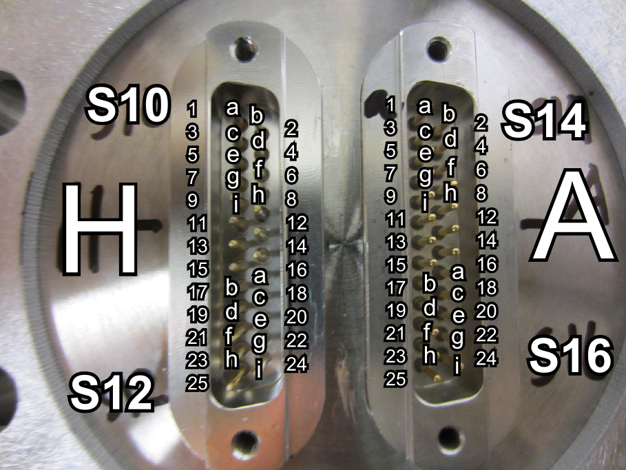
Signal Flange Pinout
Ion Chamber Cable Routing
From the preamps attached to the exterior of the target chamber a set of shielded cables are required to the DAQ. This involves the ion chamber, DAQ, and Integration sections.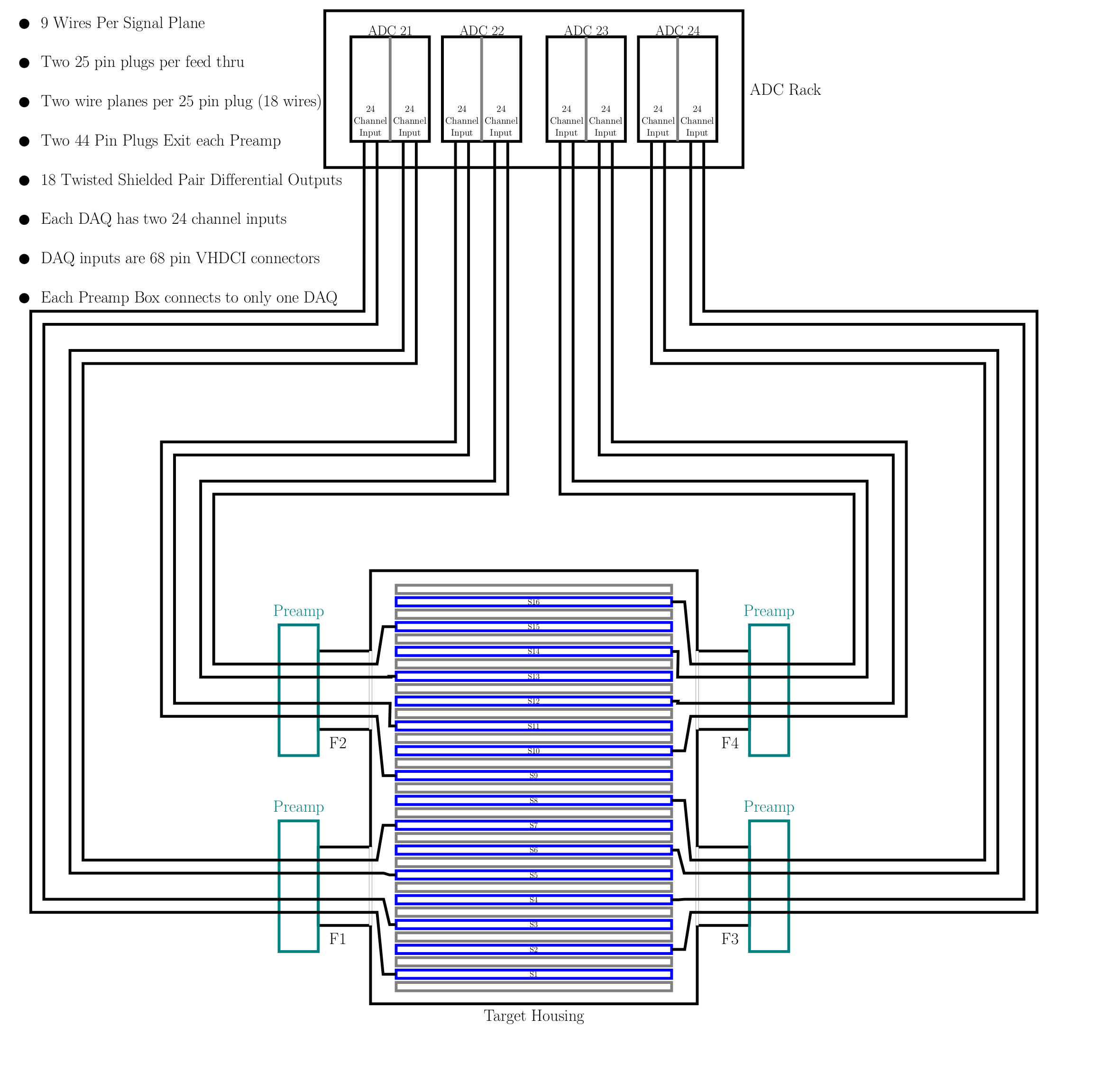
Wire Frame Diagram (PDF) (Latex/Tikz Source)
n3HeSignalCableRouting.pdf