Related Pages:
Table of Contents
Editing In Progress-2016/06/14
Chamber Simulation:
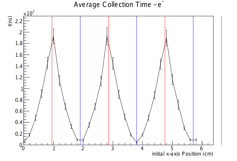
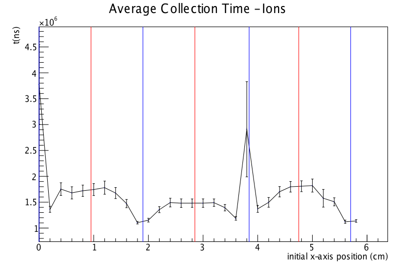
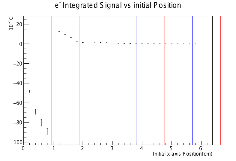
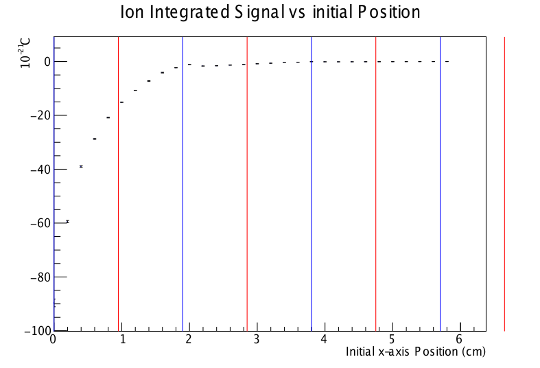
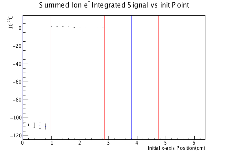
A simulation using Garfield++, a ion chamber simulation program is in progress to analyze charge collection in the chamber.The 3d finite element analysis program Elmer was used to create a 3 dimensional field map for use in the simulation. The program gmsh was used to create the mesh model of the chamber.
Code
Note: This is just a straight upload of my last working code from a year ago, while sufficient to run your own simulation it will take a bit of hacking and I don't guarantee the comments in the code explain things well. Future updates will be done to make this easier for other people to use, so I recommend emailing me before you try to make use of this so I can provide some advice, but I also did not want to hoard the code until I graduated and it disappeared with me. - M. McCreaMakefile
makefile
Gmsh
n3HeTarget.geogf_rectangle.geo
Elmer
n3HeTarget-350V.sif
Garfield++
n3Hesim.ccGasFile.C
Field Map Slices
Seven slices were taken through the field map of the target simulation to show how the field varied at each height above the center line. The target has a 12.7 cm interior radius.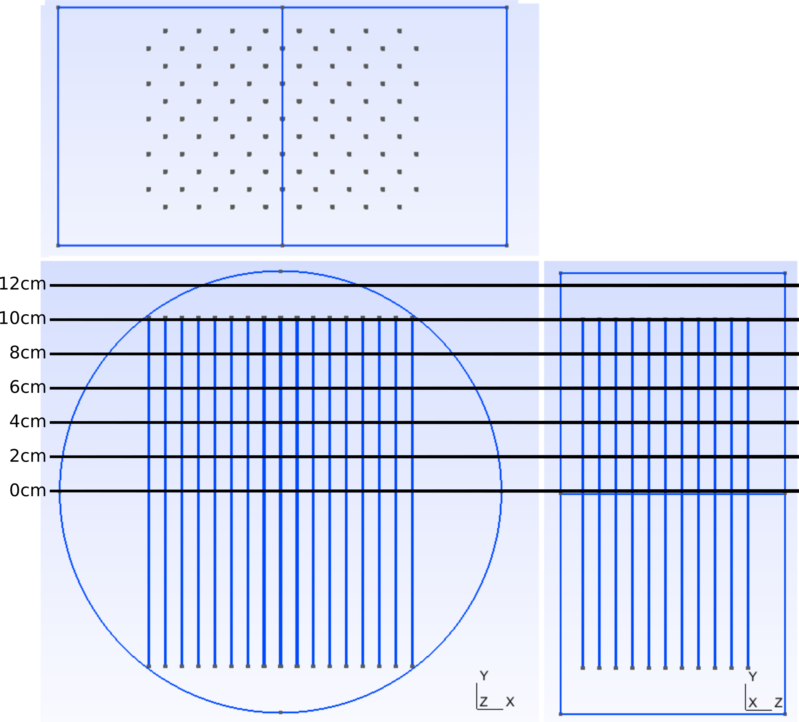
Show Slices
For the first field slice at 0 cm offset the x-axis limits are set at 12.7 cm. As the slices raise in the target chamber the colors do not cut off outside the chamber housing that is the limit of the simulation but displays as zero volts.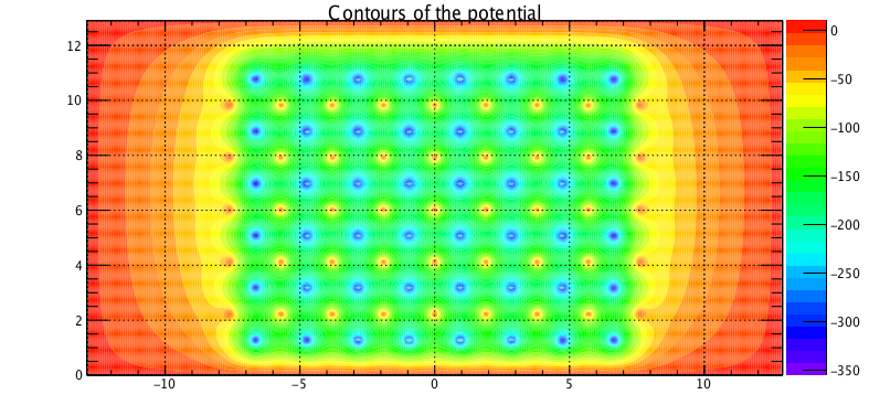 |
| Field Slice at 0 cm offset from central chamber axis. |
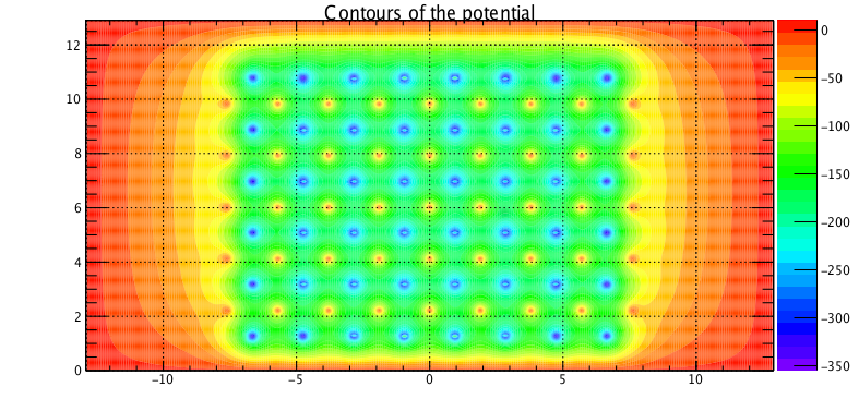 |
| Field Slice at 2 cm offset from central chamber axis. |
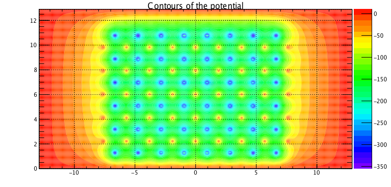 |
| Field Slice at 4 cm offset from central chamber axis. |
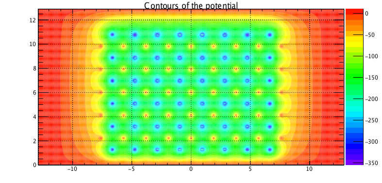 |
| Field Slice at 6 cm offset from central chamber axis. |
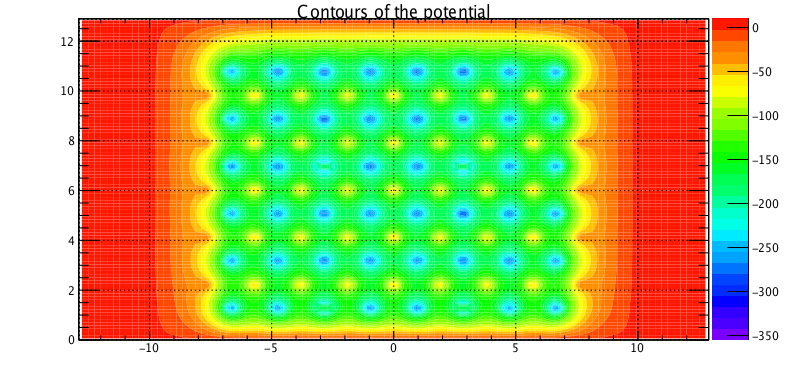 |
| Field Slice at 8 cm offset from central chamber axis.This is at the edge of the interior volume of the wire frame. |
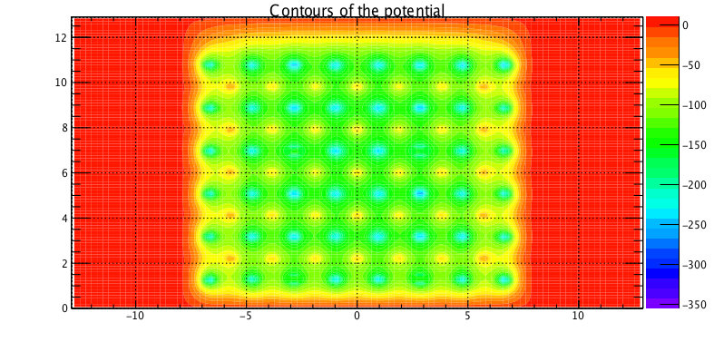 |
| Field Slice at 10 cm offset from central chamber axis. |
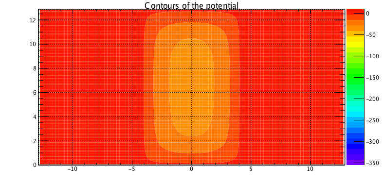 |
| Field Slice at 12 cm offset from central chamber axis. |
1D plot along vertical line
Simulation Results
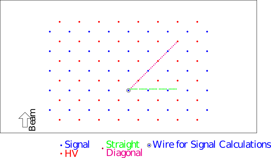
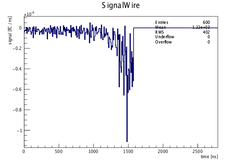 |
| Signal over time for one collection of one electron. |
Diagonal
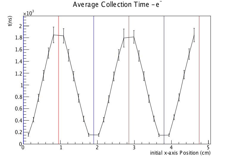
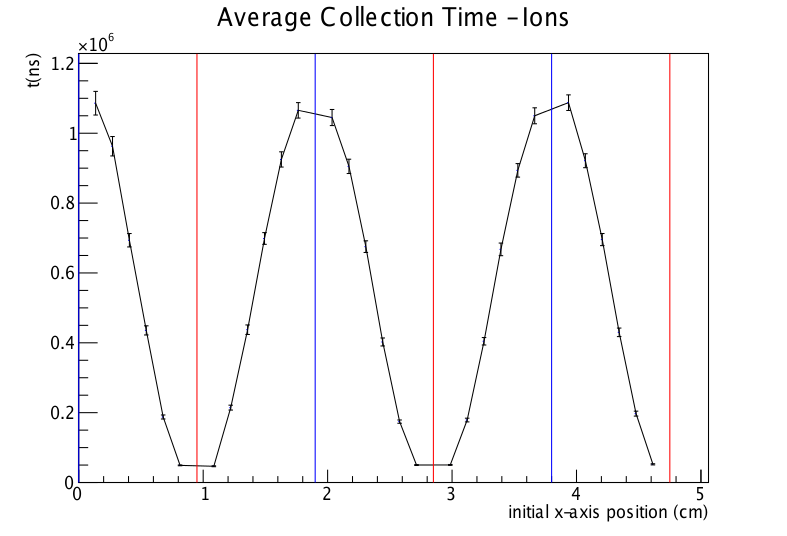
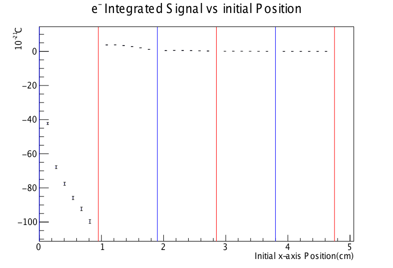
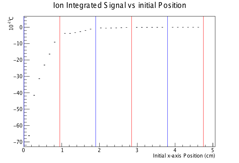
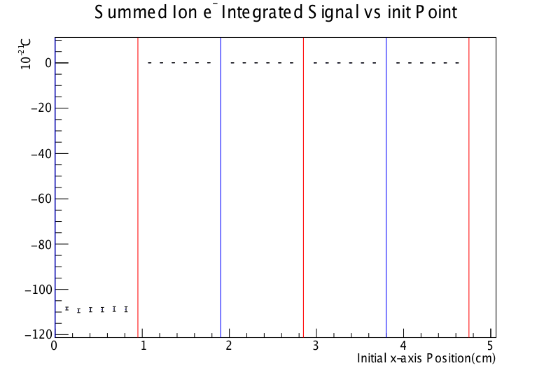
Straight line
