When we want to tell someone about an electrical device we have
made, we need to specify what is connected to what, and how. This
is most easily done using a pictoral language, in which the
electrical components are reduced to simple sketches. The elements
of this language are given in the table below. Note that we need
to distinguish between wires that are crossing each other on the
diagram from those that are actually connecting.
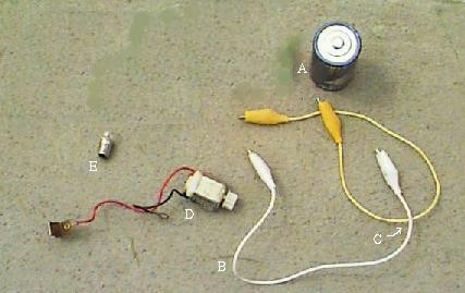
| component name | representation |
| battery (A) |  |
| wire (B) |  |
| intersecting wires |  |
| nonintersecting wires (C) |  |
| motor (D) |  |
| light bulb (E) |  |
*The simplest possible electrical device is  . It doesn't seem to do anything, but
actually it is running down the battery as fast as it can! This is
called a "short circuit," because the most common way for it to
happen is to have two wires touch accidentally, giving the current
a short cut. We all make this circuit a few times when we are first
learning about electricity. If you make this circuit, don't leave
it hooked up more than a few seconds -- your battery will go dead
after a while. . It doesn't seem to do anything, but
actually it is running down the battery as fast as it can! This is
called a "short circuit," because the most common way for it to
happen is to have two wires touch accidentally, giving the current
a short cut. We all make this circuit a few times when we are first
learning about electricity. If you make this circuit, don't leave
it hooked up more than a few seconds -- your battery will go dead
after a while. |
 |
shows
the filament as a wiggly line or a little loop, inside a circle representing the
glass bulb. In an actual light bulb,
the one end of the filament is connected to the button
on the bottom of a bulb and the other is connected to the threaded metal
part of the base. These parts are not shown in the diagram for a bulb;
in a circuit diagram the connecting wires go directly to the ends of the
filament 
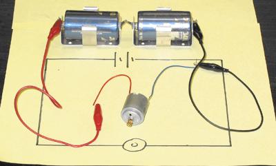
*You have already made this diagram: by connecting the wires of the motor to
the corresponding parts of the battery. Since the motor has its own
wires, we don't need to introduce any; but you could add some of
the wires from the kit, as shown in the picture. Note that the
diagram doesn't try to represent the actual shapes and lengths of
the wires. It tries to indicate the path that the current takes,
and as simply as possible. Using two wires or four wires or
seventeen wires to connect the motor to the battery would give the
same diagram. by connecting the wires of the motor to
the corresponding parts of the battery. Since the motor has its own
wires, we don't need to introduce any; but you could add some of
the wires from the kit, as shown in the picture. Note that the
diagram doesn't try to represent the actual shapes and lengths of
the wires. It tries to indicate the path that the current takes,
and as simply as possible. Using two wires or four wires or
seventeen wires to connect the motor to the battery would give the
same diagram. |
 |
*To build on the concept just introduced, you should consider the devices shown below. None of them is very interesting; only one of them does anything at all! Decide what you think is wrong with each diagram, and then click on it for another opinion.
 |
 |
 |
 |
 |
Diagrams are a way to communicate how a circuit is put together. One way to turn a diagram into an actual circuit is to redraw the diagram on a full-sized piece of paper, place each component where the diagram indicates, and then connect them together with wires that run along the lines.
Drawing diagrams on paper is easiest, but you can't readily email it to someone. If you would like to make computer-compatible drawings, see these instructions
Check the box when you are
done:
Next:make a switch