Table of Contents
Related Pages:
Ion Chamber Assembly
Steps in Assembly- Solder Wire Frames
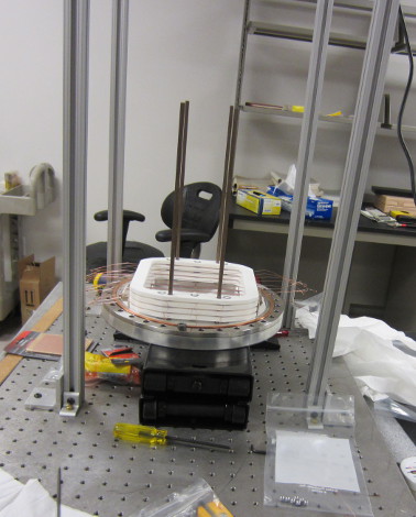
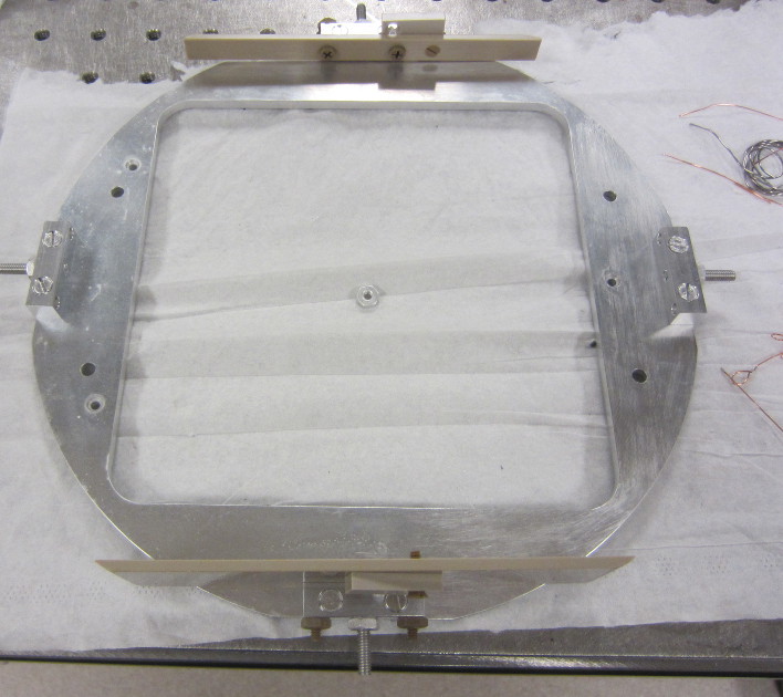
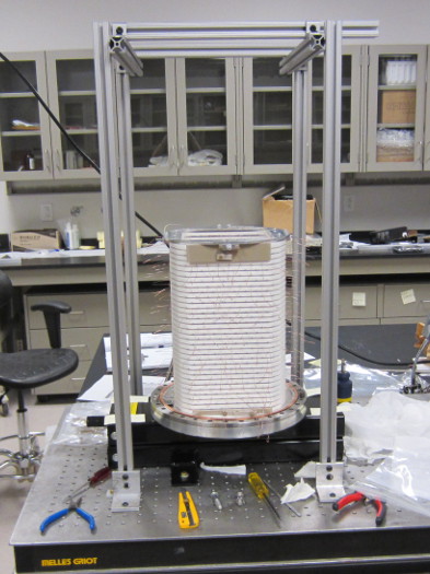
- Build and check frame stack
- Attach Readout and HV circuit boards
- Attach housing to mount flange and Feed thru flanges
- Measure alignment of frames to housing.
- Seal chamber
- Mark Frame alignment on chamber.
- Pump down to clean.
- Test Fill with He-4
- Final Fill with He-3
Wire Frame Soldering
Wire Frame Soldering Procedure Revision 0.The revision 0 soldering procedure failed probably due to excessive heating while making the solder joint with a 325 deg C soldering iron causing the first two frames tried with this procedure to crack.
Revision 1 Wire Frame Soldering Procedure
The revision 1 version of the soldering procedure documents the altered procedure after the first two unbroken wire frames that were being soldered cracked through the groove in the process of being soldered. The revision 1 procedure has been successful in soldering a dozen frames so far.
| Jig setup for soldering and tensioning two wire frames simultaneously in room A112 at JINS. |
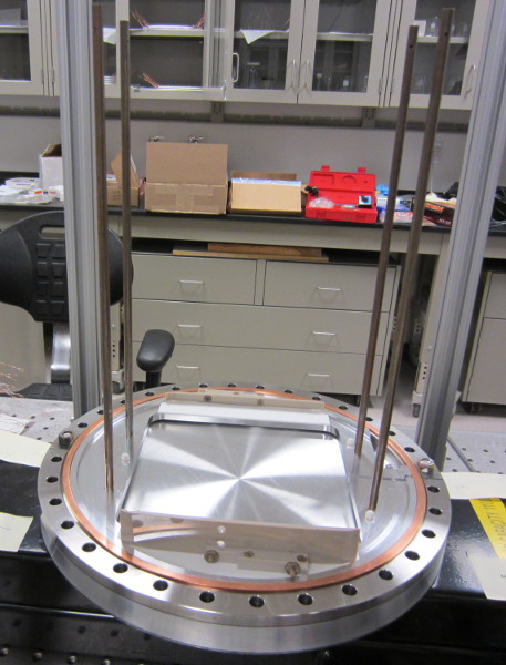
Build and Check Frame Stack
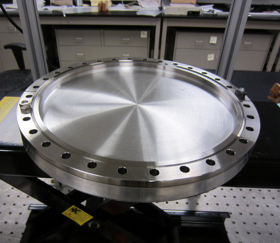
A Rage Motorcycle jack was used for the frame assembly. Some additional holes were drilled in the top of the jack to allow the end window to be bolted to the top for stability.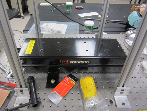
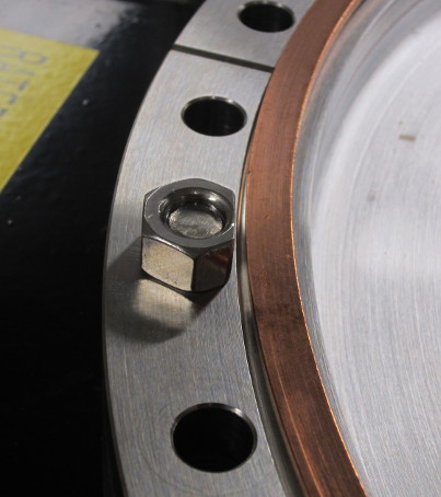
Two bolts were used to fix the window to the jack. The side of the nuts had to be filed down to make room for the copper casket that was placed over the knife edge to protect it during assembly.

Attach Readout and HV circuit boards
Measure Alignment of Frame to Housing
A Faro Arm was used to make measurements of the frame stack to determine its alignment to the target housing and to itself. Initial measurements were made to find the center of the mount flange, and then the other measurements were made relative to that point. The angle of the top plate and a series of measurements were made along the side of the frame stack to determine how straight it was. Details are in eLog entry 25.Measurement points on the frame stack and mount flange with the Faro arm:
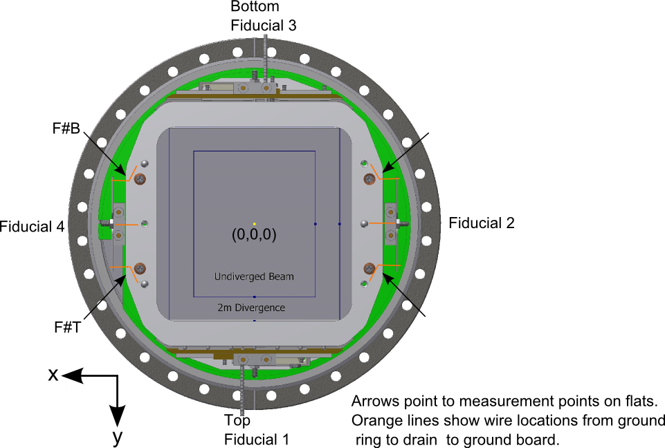
Frame angle relative to the X-axis change from Pi/2 radians:
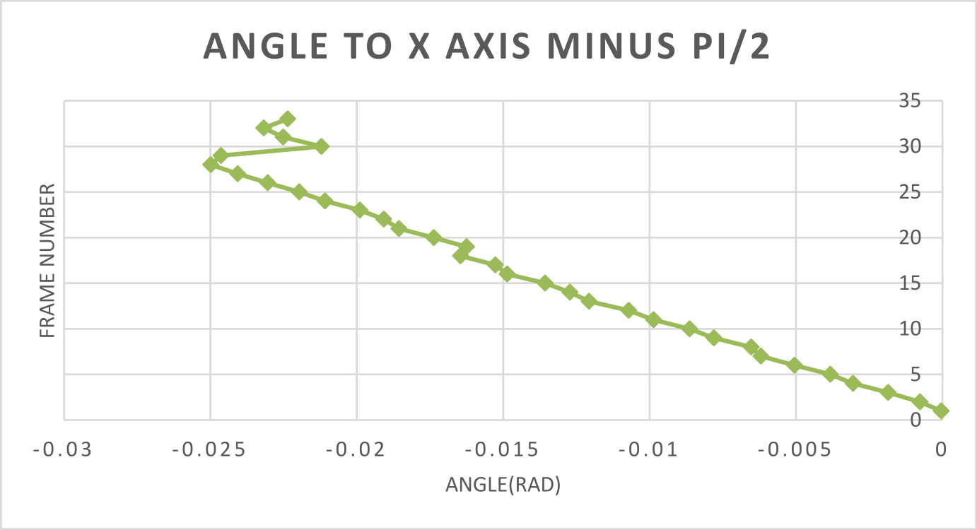
As can been seen there is an approximate 25 milliradian twist over the length of the frame stack that is fairly consistent across the stack except at the location of the 30th frame.
Interior of Housing Prior to Assembly
| Interior of Target Chamber with one end window |
| A sheet of kapton had 8 holes cut in it to allow access to the feed thrus while being placed in the interior of the housing to prevent sparking from the HV wires to the feed thru. While teflon sheet and ceramic bead shielding was used over most of the HV wiring this give an additional defense along the interior. |
Attach housing to mount flange and Feed thru flanges
Approximately 12.5" inches of lift is needed to raise the frame stack to the housing. A motorcycle lift has been purchased for this as it has both a large surface area and a sufficient height for the lift operation. The large surface area allow the jack to be bolted to the table and the the mount flange to be bolted to the jack.
The current plan is to assemble the frame stack on top of the jack bolted to the table. This loses some of the benefits of the flatness of the optical table during assembly but removes and necessity of moving the frame stack before the housing is attached.
A jack is desired for this operation as it will be a slow lift to give time for the signal and HV cables to be threaded thru the various feed thrus.
| Chamber with both windows off suspended over frame stack on tslot stand. The jack under the frame stack was used to raise the stack up to the housing. |
| Target chamber has begun to be raised on the jack and the strings on the cables have been pulled up through the feed thrus. |
| Housing in place over the frame stack and some initial bolts in place to hold the housing in place around the frame stack. |