Related Pages:
Installation in Beam Line:
A lift plan was prepared to describe the process for lifting the target chamber into place on the beam line:Ion Chamber 103014-ORNL-544-092013-Ordinary Lift Plan.pdf
Photos of Lifting Ion Chamber onto the Beam Line 11/06/2014:
Proposed Install and Rotation Methods:
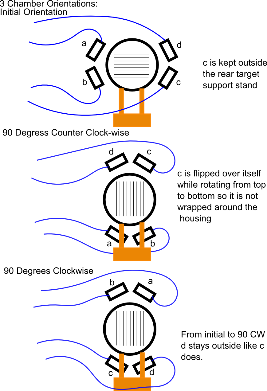
When installed in the beam the target chamber will need to rotated axially from horizontal to either of two vertical orientations. For this the signal flanges were rotated 90degress from aligning the cables with the beam axis. Below is a diagram showing how the 4 cables can be run with some of the cables being kept outside the 4 point mount to allow it to be flipped up or down taking a half twist but being kept out of the beam.